Converter diagram lab tech panel front Calibration of i/p converter 12v dc mobile charger circuit diagram
i to v converter using op amp circuit diagram - Circuit Diagram
I to p converter I to v converter using op amp circuit diagram I to p converter working animation. valve positioner. flapper nozzle
I/p converter |current to pneumatic signal converter |working & it's
What is an i/p converter? working principle, applications- electrical voltI to v converter using op amp circuit diagram Calibration of i/p converterTroubleshooting of i to p convertor (current to pneumatic converter).
I to p converter at rs 13500/piece(s)48vdc to 24vdc converter circuit diagram Shows the equivalent circuit used to analyze the converter isop systemWhat is an i/p converter? working principle, applications- electrical volt.

I to p converter in hindi || current to pressure converter
Pressure transducer circuit diagramCurrent to pressure (i/p) converter calibration procedure Current to pressure (i/p) converter calibration procedureCurrent to pressure (i/p) converter calibration procedure.
220v to 12v dc converter circuit diagram[diagram] i p converter circuit diagram Tech lab: i/p and p/i converterControl air pressure transducer i to p converter, 4-20 ma at rs 9200.

Compact current i/p to pressure converter with high accuracy
Analog to digital converter schematicConverter pressure current I/p converter calibrationCurrent to pressure (i/p) converter principle chemical engineering.
Tech lab: i/p and p/i converterConverter current Pressure converter chartCircuit diagram of the proposed integrated converter.

How to work i to p converter. bs electrical
What is an i/p converter? working principle, applications- electrical voltI/p converter 4-20ma abb i to p converter, for control valve operating at rs 1150I/p converter.
.

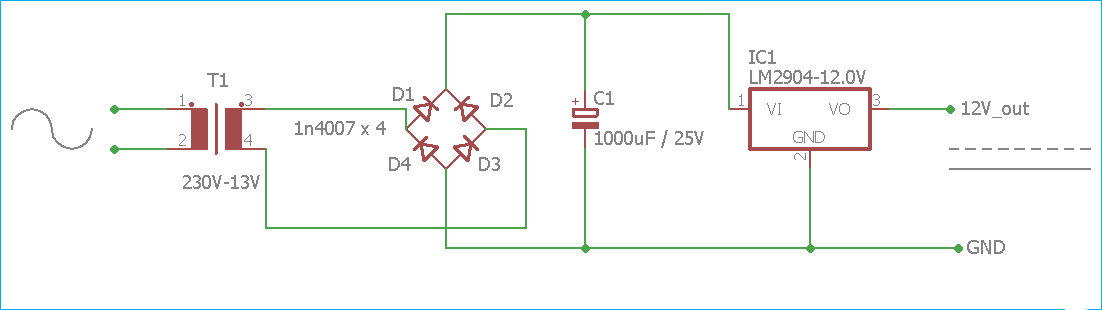
220V TO 12V DC CONVERTER CIRCUIT DIAGRAM - Electronic Projects, Power

shows the equivalent circuit used to analyze the converter ISOP system

Compact Current I/P to Pressure Converter with High Accuracy

What is an I/P converter? Working Principle, Applications- Electrical Volt

Control Air Pressure Transducer I To P Converter, 4-20 mA at Rs 9200

What is an I/P converter? Working Principle, Applications- Electrical Volt

Current to Pressure (I/P) Converter Calibration procedure

i to v converter using op amp circuit diagram - Circuit Diagram
